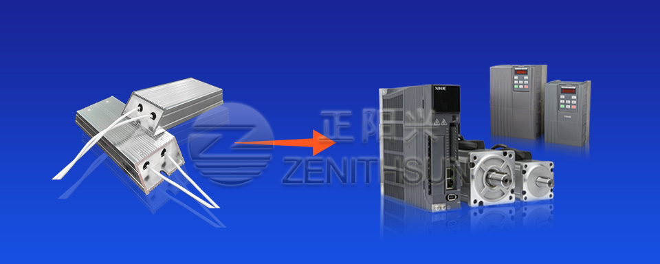
Braking resistor design, the core is to take into account the capacitor and IGBT module voltage problems, to avoid these two important devices by the high voltage of the bus washed out, these two types of components if the bad, the inverter can not work properly.
In addition to the large load deceleration occasions need to increase the braking resistor and braking unit to fast braking, in fact, if in line with the heavier, start-up time time required very fast kind, also need to brake unit and braking resistor to start with, in the past, I tried to use the inverter to drive a special punching machine, the requirements of the acceleration time of the inverter is designed as a 0.1 seconds, when the full-load start, although the load is not very heavy, but because the acceleration time is too short, the bus voltage fluctuations will also be overvoltage or overcurrent situation. But because the acceleration time is too short, the bus voltage fluctuation is very strong, there will be over-voltage or over-current, and then increase the external braking unit and braking resistor, the inverter can work normally.
Analyze, because the starting time is too short, the bus capacitor voltage instantly emptied, and the rectifier instantly have a large current charging in, causing the bus voltage suddenly high, so the bus voltage fluctuation is too strong, instantly may be more than 700 volts, coupled with the braking resistor, you can eliminate this fluctuation of high pressure in a timely manner, so that the frequency converter work in a normal state.


